An easy way to calibrate the offset coefficients for your cutter is to use the cutter laser to self-measure the distance from a contour loop to a geometry loop. Following is the procedure:
- Do not remove the paper from the cutter during this process. This way, we can maintain orthagonality while we measure the laser offset.
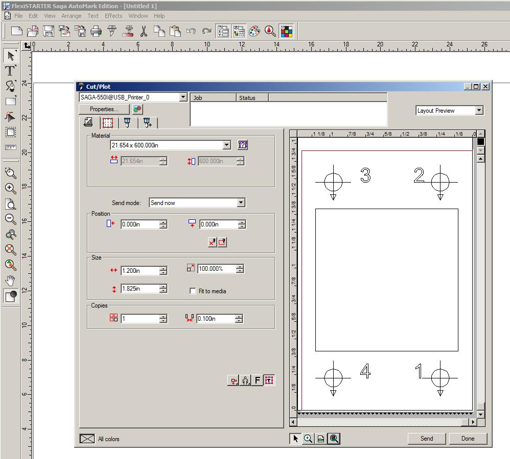
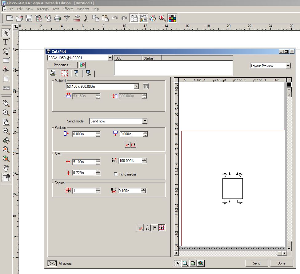
- Create a 1″ x 1″ square in Flexi Starter using the rectangle tool (fourth down on the left menu bar). In the Design Central pop up menu, set the length and width to 1″ x 1″ and set the corners to be square (Regular).

- Create a contour path around that square with an offset of 0 so the contour loop is coincident with the original geometry square. Go to Effects at the top, select Contour Cut… In the design central window, set the offset to 0 and select the green checkmark.

- Create your 4 registration marks. With the contour in place, go to Effects, select Contour Cut Marks… Select 4 point in Design Central and press the green check mark.

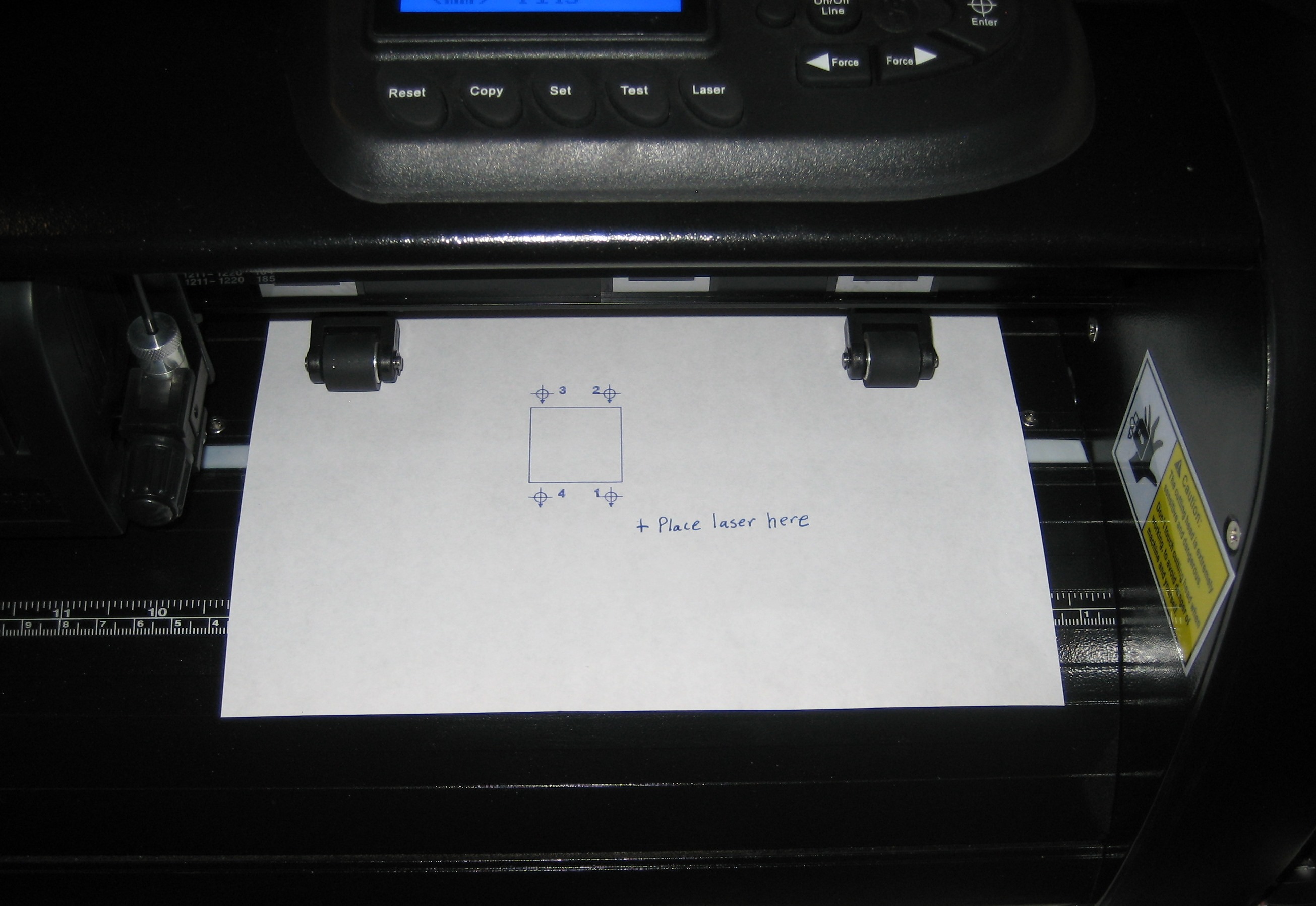
- Place a pen and paper in your vinyl cutter. Zero the pen near the middle of the paper and to the front. The contour loop will plot above and to the right of the geometry loop so we will want space above and to the right.

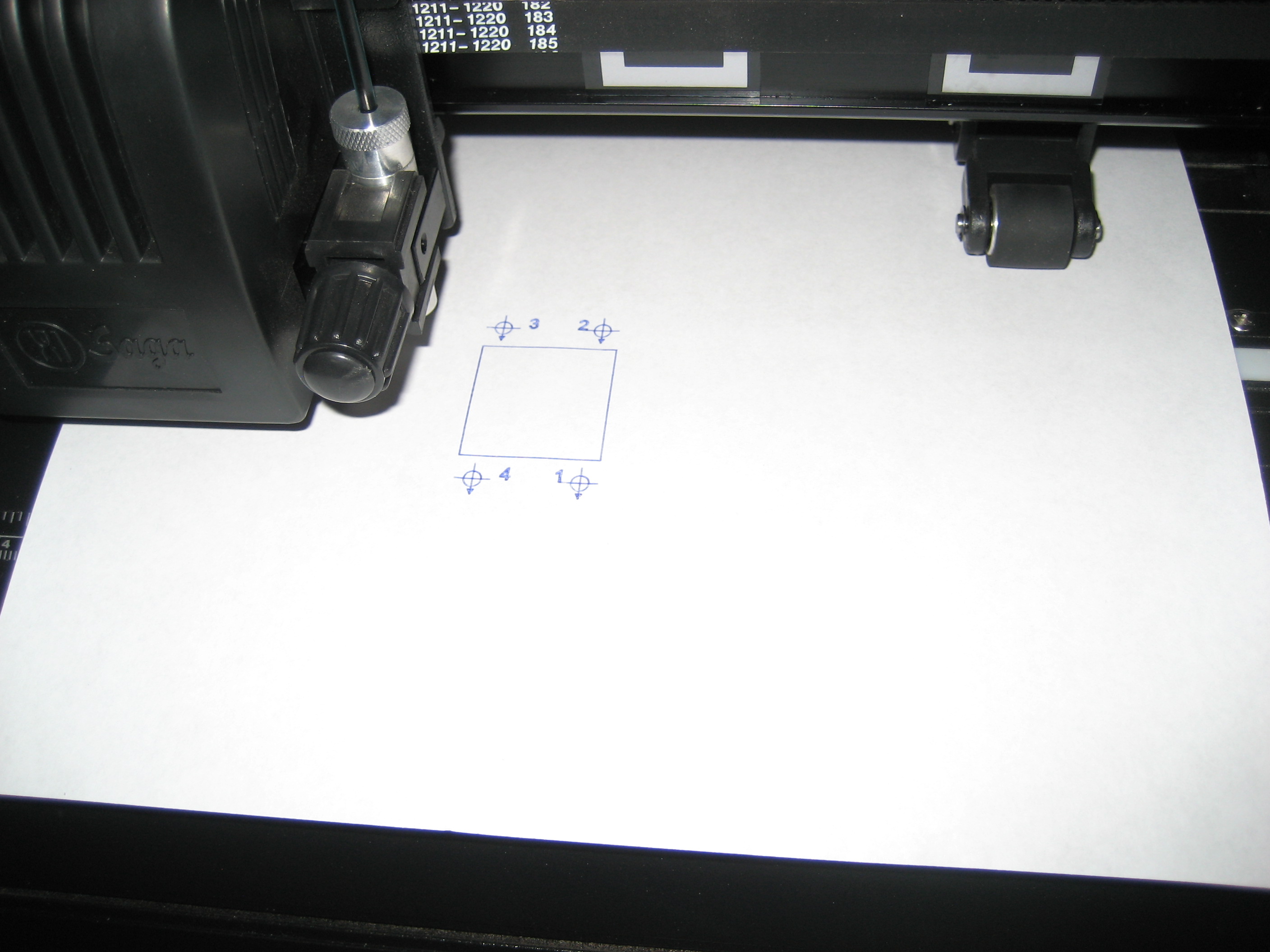
- Plot the original 1″ x 1″ square and the registration marks using the cut command.


- Move the laser so it is below and to the right of the first registration mark. Flexi will not allow negative numbers to be used during the registration process. Rezero the origin by selecting the Enter button on the cutter.

- Run the contour cut using the Contour Cut button (just to the right of the cut button on the top menu bar). The Cut Contour window will pop up.
- Under the cutter is a button called Properties… on the Cut Contour pop up window, select this tab. The third tab to the right is the Cut tab in the Default Job Properties pop up window, select the Cut tab. On the Cut tab you will find the Cutter Options… button on the bottom, select this. You will see the Before Job window. The Offset X and Offset Y is where the laser offsets will go. Select both boxes and put in 0 and 0 for the X and Y offsets. Select the Apply button. Close the Before Job window and the Default Job Properties window.

- Select Send from the Cut Contour screen, this will allow us to send the contour cut to the cutter. Select the Interactive alignment (Manual) options from the Alignment pop up window. Select OK. The Interactive alignment window will pop up. Using the arrows on your keyboard move the laser to the first registration mark. NOTE, IT IS VERY HELPFUL TO HAVE A REMOTE KEYBOARD OR TO HAVE YOUR KEYBOARD NEAR YOUR CUTTER WHEN DOING THIS. Select OK when complete. Do the same for positions 2, 3 and 4.
- A pop up box will say Please put knife back in cutter and click OK to start cutting. Select OK and the contour cut will be executed.
- The contour cut will be up and to the right of the original square. The distance between these two squares is equal to the distance between the laser and the cutting point.

- Place the laser back in the bottom right corner again and re-zero the cutter by pressing the enter button.
- Send the contour cut again.
- Select Interactive alignment (Manual) again.
- Using the keyboard arrows, move the laser to the top left corner of the original square.
- Record the X, Y values from the Interactive Alignment screen. For instance, 1.614 inch x 1.208 inch.
- Using the keyboard arrows, move the laser to the top left corner of the contour cut square.
- Record the X, Y values from the Interactive Alignment screen. For instance, 2.604 inch x .482 inch.
- Now, subtract the X and Y values from each other. For instance: 1.614-2.604 = -0.99″ for X and 1.208-.482 = .726″ for Y.
- These are the values for your cutter laser offsets. Flexi will want these numbers entered in mm, not inches so we should convert the value. For instance: -.99*25.4 mm/inch = -25.15 mm for X. .726*25.4 mm/inch = 18.44 mm for Y.
- Cancel out of this contour cut.
- Return to Properties, Default Job Properties, Cut tab, Cutter Options… Select the Offset X and Offset Y boxes and enter your offsets for the X and Y values. For instance, -25.15 and 18.44 in this example (use the values you calculated for your cutter). Click Apply. Note, the X value will always be negative and the Y value will always be positive. The positive X direction is left as you face the cutter and the positive Y direction is toward the back of the cutter as you face it. Although your values will be slightly different than the ones presented in this example, they should be very close to these values.
- Select done to close out of the Contour Cut screen.
- Send the contour cut again.
- Select the second tab of the options screen. On this tab you will see Drawing Colors and there will be a color called CutContour. Double click on this color.
- The settings pop up box will display. Select the Offset X and Offset Y checkboxes and enter your offset coordinates again. Select Apply and OK to close the box.
- Select Send in the bottom right and run through the contour cut alignment process making sure your carriage starts from the zero in the lower right corner. (This is necessary as Flexi will not accept negative values from the alignment process).
- Your contour cut should be very close if not directly on top of the original square.


Leave a Comment
You must be logged in to post a comment.